


Research & development
K2 Valve Research and development
1) An easy-to-install wafer check valve
The wafer check valve is a space-saving device, easy to install (even after completion of the piping system), inexpensive, and essential as a safety device in many applications.
We have completely rethought and redesigned the concept of the non-return valve to propose significant technical improvements on the valve market. At K2 we have created an excellent product adapted to the new economical, ecological and technical environment, our energy-efficient solution reduces pressure losses providing significant energy savings.
Our design office deployed its finest technical resources to facilitate the development of this project, using CAD/CAM, simulation and dimensioning tools.
2) Feasibility study
We had a core idea: to develop a device that would reduce pressure drops.
Therefore, we conducted a feasibility study to assess if our project would be beneficial or not.
The study validated the concept, and a patent was issued sometime later. Thanks to our prototypes and plan files, we patented our concept, with our specialist in intellectual property management.
3) Maximize installation compatibility
First of all, our product had to be compatible with the majority of installations. To ensure this, we had to consider each type of pipe. After studying the materials and standards, we defined the minimum internal diameter of the pipes, in order to avoid any risk of blocking the system.
The assembly of the flanges and its bolts, the placement of the valve, the disc, and its shaft are all elements and connections that have clearances, and therefore potential different placements depending on the mounting configuration. Each possible position must be studied in order to define the critical one with the highest probability of blocking.
Following this approach, we were able to tailor our product to ensure that it would work in all cases.
Our valve range extends to eight models from DN50 to DN250, and more on request. We have decided to focus our entire investigation on technical polymers, which are modern, lighter and have better properties than stainless steel or plastics for moulding.
4) Preliminary study
At equivalent DN’s, we compared the flow areas and the gain of the optimized version. The project’s profitability was a direct result of this first analysis, and the results were conclusive: our optimized check valve had just been validated.
The joints
First technical choice: the placement of the gasket between the disc and the body. One solution was to fix the gasket directly to the disc, which was the simplest solution in terms of manufacturing; the second possibility was to attach it directly to the body of the swing check valve. The second proposal was validated as it posed the lowest risk of joint tearing, which is the main risk of failure.
To reduce this potential weakness, we have carefully measured and defined the joint area. For these reasons, the O-ring appeared to be the most appropriate technical solution.
Two other O-rings are provided on the plug allowing sealing at the disc shaft. These elements have been designed and proportionally scaled according to the efforts involved. As a result, their dimensions increase with DN.
The stainless steel pining system
After designing all of our valve ranges, the products were placed in the most unfavorable positions within different industrial layouts.
This is how we discovered the second risk of anomalies: the insertion of the wafer check valve in the wrong direction (shaft facing down).
We eliminated this risk by designing a custom metal pin inserted at the top of the valve.
Determination of pressure losses
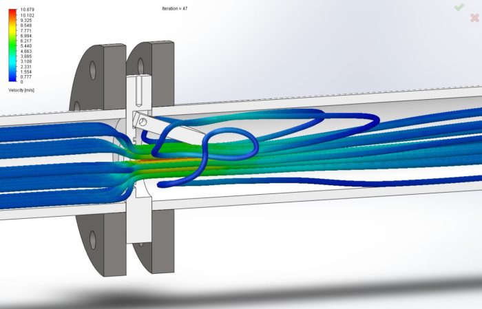
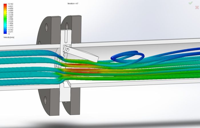
The simulation quantified with precision the gains obtained with our optimized version. Even if the comparison of the passage surfaces or flow areas, gave us a first approximation, we ran a detailed analysis to determine the underlying energy gain when using our optimized check valve within a pipe, in function to the flow rate.
We used powerful computer-aided design and fluid simulation tools to determine the pressure drops generated by our different products. These results, derived from numerical simulations, were verified using spreadsheets, as well as analytical and computational studies to test our underlying assumptions.
Results
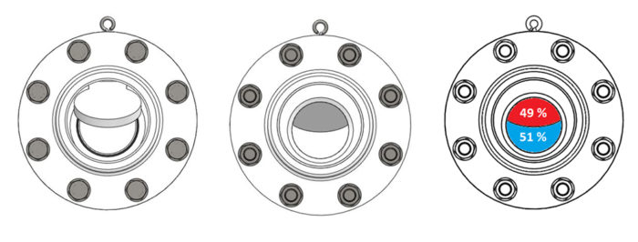
STANDARD MODEL
Percentage of reduction in the pressure drop of the optimized model compared to the standard model.
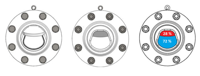
OPTIMIZED MODEL
Percentage of reduction in flow speed trough the narrowest section, please note that an increased flow speed necessarily favors turbulence when encountering singularities.
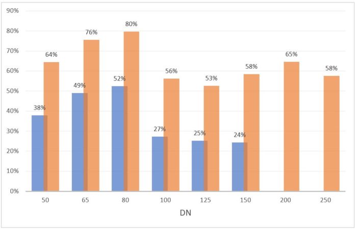
In orange: percentage of reduction in the pressure loss of the optimized model compared to the standard model.
In blue: Percentage of reduction in flow speed trough the narrowest section, please note that an increased flow speed necessarily favors turbulence when encountering singularities.
In conclusion, the pressure losses are two to five times lower on the optimized non-return valve!
How can this be translated into practice?
Your pump will simply consume about two to five times less energy on the relevant pipe section!
In addition, there is a good chance that the valve will be the most loss-making element in your entire installation, so invest in the right place!